Accesories
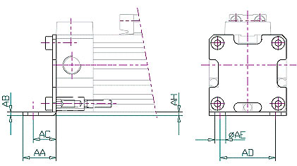
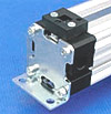
SLXP Mounting brackets
|
|
|
|
|
|
AA
|
AB
|
AC
|
AD
|
AE
|
AH
|
 |
|
|
|
|
|
|
|
|
|
SLXP/018
|
Ø 18
|
15
|
2
|
10
|
20
|
Ø 6
|
2
|
|
SLXP/025
|
Ø 25
|
18
|
2
|
12,5
|
30
|
Ø 6
|
2
|
|
SLXP/032
|
Ø 32
|
20
|
2,5
|
13,5
|
40
|
Ø 7
|
3
|
|
SLXP/040
|
Ø 40
|
30
|
3
|
17,5
|
50
|
Ø 9
|
3,5
|
|
SLXP/050
|
Ø 50
|
28
|
3
|
20
|
60
|
Ø 9
|
3
|
|
SLXP/063
|
Ø 63
|
30
|
3
|
21
|
75
|
Ø 11
|
4,5
|
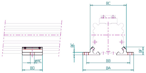
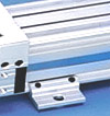
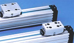
SLP Middle support
|
|
|
|
|
AE
|
AH
|
BA
|
BB
|
BC
|
BD
|
BE
|
BF
|
 |
|
|
|
|
|
|
|
|
|
|
|
SLP/018
|
Ø 18
|
Ø 6
|
2
|
56
|
46
|
36,5
|
23
|
2,5
|
8,25
|
|
SLP/025
|
Ø 25
|
Ø 6
|
2
|
70
|
60
|
50
|
28
|
3,5
|
11
|
|
SLP/032
|
Ø 32
|
Ø 7
|
3
|
85
|
73
|
61,5
|
33
|
4
|
13,8
|
|
SLP/040
|
Ø 40
|
Ø 9
|
3
|
105
|
90
|
75
|
38
|
4,5
|
16
|
|
SLP/050
|
Ø 50
|
Ø 9
|
3
|
122
|
106
|
91
|
43
|
5
|
19
|
|
SLP/063
|
Ø 63
|
Ø 11
|
4,5
|
144
|
125
|
107
|
48
|
6
|
22
|
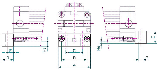
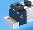
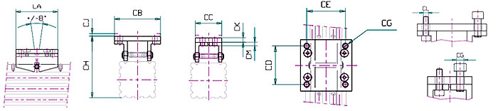
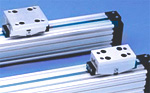
SLF Mounting block
|
|
|
|
|
A
|
B
|
C
|
D
|
E
|
F
|
G
|
H1
|
H2
|
Śruby
|
 |
|
|
|
|
|
|
|
|
|
|
|
|
|
SLF/018
|
Ø 18
|
30
|
23,5
|
14
|
10
|
14,5
|
5
|
Ø 4,5
|
6
|
2
|
M3 x 14
|
|
SLF/025
|
Ø 25
|
42
|
33
|
22
|
15
|
17
|
7,5
|
Ø 5,5
|
6
|
2
|
M4 x 20
|
|
SLF/032
|
Ø 32
|
52
|
41
|
23,5
|
15
|
20
|
7,5
|
Ø 7
|
6
|
3
|
M5 x 20
|
|
SLF/040
|
Ø 40
|
63
|
51
|
30
|
15
|
23
|
7,5
|
Ø 9
|
8
|
3
|
M6 x 20
|
|
SLF/050
|
Ø 50
|
78
|
63
|
39
|
16
|
26
|
8
|
Ø 9
|
8
|
3
|
M8 x 20
|
|
SLF/063
|
Ø 63
|
93
|
78
|
52
|
20
|
27,5
|
10
|
Ø 11
|
8
|
4,5
|
M8 x 20
|
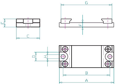
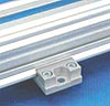
SLPP Middle support
|
|
|
|
|
A
|
B
|
C
|
D
|
E
|
F
|
G
|
H
|
 |
|
|
|
|
|
|
|
|
|
|
|
SLPP/018
|
Ø 18
|
56
|
46
|
30
|
12
|
11
|
6
|
50,6
|
Ø 5,5
|
|
SLPP/025
|
Ø 25
|
70
|
60
|
30
|
12
|
13
|
6
|
65,5
|
Ø 5,5
|
|
SLPP/032
|
Ø 32
|
85
|
73
|
40
|
12,5
|
15
|
6
|
77,5
|
Ø 6,6
|
|
SLPP/040
|
Ø 40
|
105
|
90,5
|
40
|
16
|
18
|
8
|
90,5
|
Ø 9
|
|
SLPP/050
|
Ø 50
|
122
|
105
|
40
|
16
|
20,5
|
8
|
107,5
|
Ø 9
|
|
SLPP/063
|
Ø 63
|
144
|
125
|
50
|
19
|
21,5
|
8
|
122,5
|
Ø 11
|
Deflection diagram
|
Fz
at deflection of 0,5 [mm]
|
Fz at
deflection of
1 [mm]
|
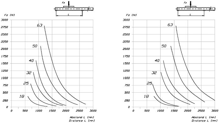
When using very long cylinders or
applying heavyloads, the tube deflection is to be taken into
consideration. One or more middle supports are to be used according to
the admissible deflection.
Example :
A cylinder ∅25 should deflect by a maximum of 0.5 mm when
applying a force FZ of 500N.
According to the diagram the cylinder can be 750 mm long.
Longer cylinders must have a middle support.
Other possibilities
In case very long cylinders are installed without supports, an
additional profile can be used as a support.
Examples: all versions with middle support and standard profiles.
|
SLM Swinging bridge
The
swinging bridge will be used where additional guiding is mounted in
connection with a rodless cylinder.
The swinging bridge transfers the action power to the guiding element
without any restraint.

|
|
|
|
|
CA
|
CB
|
CD
|
CE
|
CG
|
CH
|
CJ
|
CK
|
CM
|
CL
|
 |
|
|
|
|
|
|
|
|
|
|
|
|
|
SLM/018
|
Ø 18
|
50
|
41,5
|
30
|
34
|
M5
|
54
|
2,5
|
4
|
4
|
M4
|
|
SLM/025
|
Ø 25
|
60
|
50
|
40
|
38
|
M5
|
70
|
3
|
4
|
4
|
M4
|
|
SLM/032
|
Ø 32
|
70
|
60
|
50
|
48
|
M6
|
86
|
3,5
|
6
|
6
|
M5
|
|
SLM/040
|
Ø 40
|
80
|
80
|
60
|
60
|
M8
|
107
|
4,5
|
8
|
8
|
M6
|
|
SLM/050
|
Ø 50
|
90
|
95
|
70
|
70
|
M8
|
123
|
4,5
|
8
|
8
|
M6
|
|
SLM/063
|
Ø 63
|
100
|
120
|
80
|
90
|
M10
|
145,5
|
5
|
8
|
8
|
M8
|
SLMK Swinging bridge
|
|
|
|
|
CA
|
CC
|
CD
|
CF
|
CG
|
CH
|
CJ
|
CK
|
CM
|
CL
|
 |
|
|
|
|
|
|
|
|
|
|
|
|
|
SLMK/018
|
Ø 18
|
50
|
25,5
|
30
|
9
|
M5
|
54
|
2,5
|
4
|
4
|
M4
|
|
SLMK/025
|
Ø 25
|
60
|
30
|
40
|
14
|
M5
|
70
|
3
|
4
|
4
|
M4
|
|
SLMK/032
|
Ø 32
|
70
|
37
|
50
|
16
|
M6
|
86
|
3,5
|
6
|
6
|
M5
|
|
SLMK/040
|
Ø 40
|
80
|
47
|
60
|
22
|
M8
|
107
|
4,5
|
8
|
8
|
M6
|
|
SLMK/050
|
Ø 50
|
90
|
56
|
70
|
30
|
M8
|
123
|
4,5
|
8
|
8
|
M6
|
|
SLMK/063
|
Ø 63
|
100
|
73
|
80
|
40
|
M10
|
145,5
|
5
|
8
|
8
|
M8
|
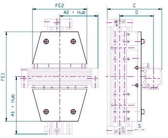
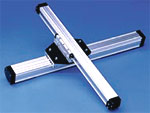
SLK cross support
The
cross support connects two guiding cylinders to a two-axis-system.
Guiding cylinders have to be ordered separately.
|
|
|
|
Kombinacja
siłowników
|
A1
|
A2
|
C
|
D
|
FE1
|
FE2
|
S
|
 |
|
|
|
|
|
|
|
|
|
|
SLK/018-018
|
D18 –
D18
|
80
|
80
|
84
|
54
|
103
|
103
|
6
|
|
SLK/025-018
|
D25 –
D18
|
100
|
80
|
100
|
64
|
131
|
103
|
8
|
|
SLK/025-025
|
D25 –
D25
|
100
|
100
|
114
|
72
|
131
|
131
|
8
|
|
SLK/032-018
|
D32 –
D18
|
120
|
80
|
112
|
71
|
171
|
103
|
8
|
|
SLK/032-025
|
D32 –
D25
|
120
|
100
|
128
|
81
|
171
|
131
|
10
|
|
SLK/032-032
|
D32 –
D32
|
120
|
120
|
140
|
88
|
171
|
171
|
10
|
|
SLK/040-025
|
D40 –
D25
|
150
|
100
|
142
|
89,5
|
220
|
131
|
10
|
|
SLK/040-032
|
D40 –
D32
|
150
|
120
|
154
|
96,5
|
220
|
171
|
10
|
|
SLK/040-040
|
D40 –
D40
|
150
|
150
|
168
|
105
|
220
|
220
|
10
|
|
SLK/050-032
|
D50 –
D32
|
180
|
120
|
171
|
106
|
280
|
171
|
10
|
|
SLK/050-040
|
D50 –
D40
|
180
|
150
|
187
|
116,5
|
280
|
220
|
12
|
|
SLK/050-050
|
D50 –
D50
|
180
|
180
|
204
|
126
|
280
|
280
|
12
|
|
SLK/063-040
|
D63 –
D40
|
215
|
150
|
204,5
|
126,5
|
333
|
220
|
12
|
|
SLK/063-050
|
D63 –
D50
|
215
|
180
|
221,5
|
136
|
333
|
280
|
12
|
|
SLK/063-063
|
D63 –
D63
|
215
|
215
|
239
|
146
|
333
|
333
|
12
|
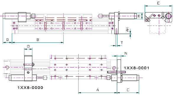
SLA Stop adjustment
|
|
|
|
|
Asl-g/Asl-gc
|
AH
|
Bsl-g/Bsl-gc
|
C
|
D
|
E
|
M
|
N
|
O
|
T
|
|
|
|
|
|
|
|
|
|
|
|
|
|
|
SLA/018
|
Ø 18
|
80/57,5
|
2
|
113/90,5
|
32
|
max. 25
|
57
|
M10x1
|
8
|
15
|
M3 x 10
|
|
SLA/025
|
Ø 25
|
100/67,5
|
2
|
117,5/85
|
37
|
max.40
|
72
|
M14x1,5
|
10
|
20
|
M4 x 10
|
|
SLA/032
|
Ø 32
|
120/77,5
|
3
|
135,5/90
|
70
|
max. 30
|
84
|
M14x1,5
|
12
|
20
|
M5 x 12
|
|
SLA/040
|
Ø 40
|
150/95
|
3
|
165/110
|
65
|
max. 50
|
105
|
M25x1,5
|
15
|
30
|
M6 x 15
|
|
SLA/050
|
Ø 50
|
180/105
|
3
|
195/140
|
80
|
max. 65
|
126
|
M25x1,5
|
15
|
30
|
M8 x 20
|
|
SLA/063
|
Ø 63
|
215/125
|
4,5
|
250/160
|
80
|
max. 65
|
140
|
M25x1,5
|
15
|
40
|
M8 x 20
|
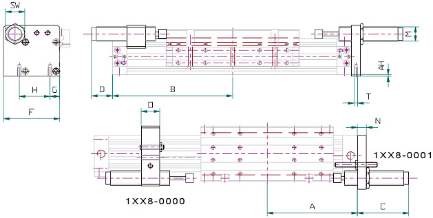
SLAE Stop adjustment
|
|
|
|
|
|
Asl-g/Asl-gc
|
AH
|
Bsl-g/Bsl-gc
|
C
|
D
|
F
|
G
|
H
|
M
|
N
|
O
|
SW
|
T
|
|
|
|
|
|
|
|
|
|
|
|
|
|
|
|
|
|
SLAE/018
|
Ø 18
|
80/57,5
|
2
|
113/90,5
|
32
|
max. 25
|
43,5
|
8
|
23,5
|
M10x1
|
8
|
15
|
13
|
M3 x 10
|
|
SLAE/025
|
Ø 25
|
100/67,5
|
2
|
117,5/85
|
37
|
max.40
|
57
|
12,5
|
33
|
M14x1,5
|
10
|
20
|
17
|
M4 x 10
|
|
SLAE/032
|
Ø 32
|
120/77,5
|
3
|
135,5/90
|
70
|
max. 30
|
70
|
14,5
|
41
|
M14x1,5
|
12
|
20
|
17
|
M5 x 12
|
|
SLAE/040
|
Ø 40
|
150/95
|
3
|
165/110
|
65
|
max. 50
|
93
|
16
|
51
|
M25x1,5
|
15
|
30
|
32
|
M6 x 15
|
|
SLAE/050
|
Ø 50
|
180/105
|
3
|
195/140
|
80
|
max. 65
|
102
|
22,5
|
63
|
M25x1,5
|
15
|
30
|
32
|
M8 x 20
|
|
SLAE/063
|
Ø 63
|
215/125
|
4,5
|
250/160
|
80
|
max. 65
|
118,5
|
20
|
78
|
M25x1,5
|
15
|
40
|
32
|
M8 x 20
|
SLV Reed switch
|